Embedded control system (DC motor car)
Team project devoted to building a control system (PID) for regulating a motor car's speed.

Introduction
This class project was a group effort, taking place during the 2019-2020 school year at the University of Strasbourg. With the electrical engineering program partly geared towards automation, the task of regulating a model car’s speed permitted us to apply what we had learned in our control courses to a real system. Unfortunately, due to Covid-19 obligating the shutdown of the university and its teaching laboratories, we were unable to finish the project as well as take ample photos and videos. With that said, what follows is a summary of the work that we had managed to accomplish in time.
Concept
Here’s how it worked:
- The speed of our DC motor model car was measured by employing optical sensors and perforated disks that rotated synchronously with the motors. Electrical impulsions were sent to an Arduino nano when the disc’s holes were passed in front of the optical sensor.
- By using these impulsions and knowing the number of perforations present on a disk, the system’s software could keep track of the time it took for one full disk revolution. With a little geometry, the speed was able to be calculated.
- To visualize this data while the car was in motion, ZigBee wireless RF modules were employed for communication between two Arduino nanos. On the receiver side, the speed information was then transferred to a LCD screen for simple viewing.
- The speed was regulated using a closed negative feedback loop and a PID controller. The gains of the different controller elements were experimentally adjusted to illustrate varying system responses.
Schematic
Designed in EAGLE, here is the electronic schema for the system:
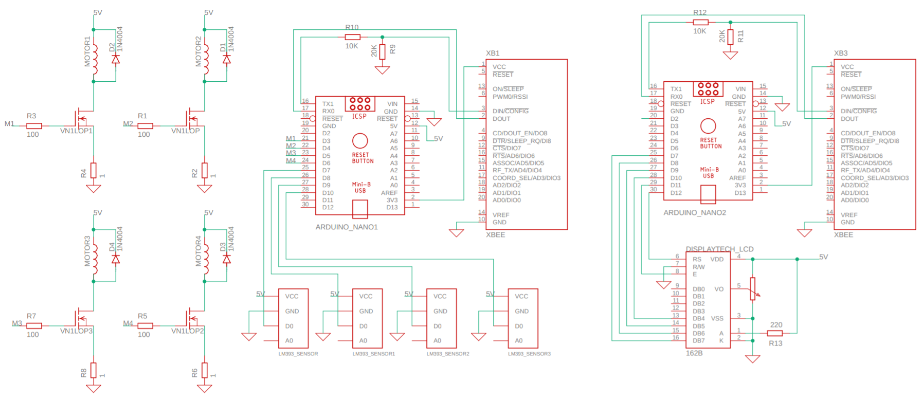
As we can see on the left side of the diagram, there are 4 DC motors (modeled by 4 inductors) and the speed of these motors is determined by the gate voltage of the MOSFET drivers. This gate voltage is controlled by PWM with the Arduino’s digital pins. A 100 ohm resistor is placed between the PWM pin and the transistor’s gate to limit the in-rush current during switching.
Next, the LM393 optical sensors are connected to the first Arduino which communicates with the sender ZigBee. It’s pertinent to note that a voltage divider is necessary for the UART communication and to avoid damaging the RF modules, as the Arduino is set at 5 V level and the ZigBee at 3.3 V.
On the receiver side, the same voltage divider and Arduino/ZigBee pair is present, however a Display Tech LCD is also included to display the speed information of the model car.
Code
In the following example, the software for the speed regulation of only one motor is included. The program for this control system is relatively simple. As touched upon in the introduction, a counter variable is used and increased by one once a hole of the disk passes in front of the optical sensor. Thanks to the millis() function of the Arduino, the time it takes for one full revolution is determined. Knowing the circumference of the perforated disk, a simple distance/time division gives the motor’s speed which is then displayed to the serial monitor.
1
2
3
4
5
6
7
8
9
10
11
12
13
14
15
16
17
18
19
20
21
22
23
24
25
26
27
28
29
30
31
32
33
34
35
36
37
38
39
40
41
42
43
44
45
46
47
48
49
50
51
52
53
54
55
56
57
58
59
60
61
62
63
64
65
66
67
68
69
70
71
72
73
74
75
76
77
78
79
80
81
82
83
84
85
//Pin for reading optical sensor impulsions
#define fourchePin 2

//Gate pin for a MOSFET driver
#define InputGrille 3
#define TWO_PI 6.283185307179586476925286766559

#include <PID_v1.h>

//PID controller variables and gain values
double Setpoint, Input, Output,Kp = 1,Ki = 1000,Kd = 10;

//Setup controller
PID myPID(&Input, &Output, &Setpoint,Kp,Ki,Kd, DIRECT);

volatile int count,countold,trou=20;

//tempsRotDebut: time at the beginning of a revolution
//tempsRotFin: time at the end of the revolution
//tempsRotTotal: difference between these two times
unsigned long temps = 0, tempsRotDebut=0, tempsRotFin=0, tempsRotTotal=0;

//125 cm for the disk radius
float rayonDisc=0.0125,vitesse=0.0;

void setup()
{
  //PID controller definitions
  Input = vitesse;
  Setpoint = 3;

  //Turn on PID
  myPID.SetMode(AUTOMATIC);

  //Initialize counter at 0
  count = 0;
  countold = 0;

  pinMode(fourchePin, INPUT);

  //Interrupt to catch optical sensor impulsion
  attachInterrupt(digitalPinToInterrupt(fourchePin), impulseTrigger, FALLING);

  Serial.begin(2000000);
  Serial.println("VITESSE DE VOITURE");

}


void loop()
{
  //this code only occurs if an impulsion is detected
  if (countold != count)
  {
    if(count>=trou){
      //Calculation: time it takes for one full revolution
      tempsRotFin=temps;
      tempsRotTotal=tempsRotFin-tempsRotDebut;
      tempsRotDebut=tempsRotFin;

      //Speed calculation (km/hr)
      vitesse=3600*TWO_PI*rayonDisc/(tempsRotTotal);

      //Reset the counter at 0 (new revolution)
      count=0;

      //Display speed
      Serial.print("   VITESSE (km/h): ");
      Serial.println(vitesse,5);
    }

    countold = count;

    //Control system
    Input = vitesse;
    myPID.Compute();
    analogWrite(InputGrille,Output);
  }
}

void impulseTrigger()
{
  temps = millis();
  count++;
}
This speed is then compared with the user’s reference speed, and the error is then passed into the PID controller. The resulting command adjusts the PWM value for the MOSFET drivers (if necessary).
Once the ZigBees were configured according to their provided documentation, the displaying of the speed information was straightforward. Thanks to Arduino’s included LiquidCrystal library, it was only necessary to initialize the LCD.
1
2
3
4
5
6
7
8
9
10
11
12
13
14
15
16
17
18
19
20
21
22
#include <LiquidCrystal.h>

byte rs = 2, en = 3, d4 = 4, d5 = 5, d6 = 6, d7 = 7;
char message;
LiquidCrystal lcd(rs, en, d4, d5, d6, d7);

void setup() {
 lcd.begin(16, 2);
 Serial.begin(9600);
}

void loop() {
  if((Serial.available() > 0)){
    lcd.clear();

    while((Serial.available() > 0)){
      message=Serial.read();
      delay(1);
      lcd.print(message);
    }
  }
}
Conclusion
As the health crisis inhibited us from completing the project, we were not able to implement certain functionalities. If the project is ever further developed, these are the additions that we would recommend:
- A rechargeable battery source for the model car and the ZigBee sender
- A variable reference defined by the user in the control system. Two-way communication would thus be necessary between the two ZigBees
- H-bridges for the DC motors allowing for braking and thus reversibility of the motor direction