Clap activated switch (Clapper)
Construction of a clap-activated relay switch with A/D conversion and embedded code reducing false positive triggering

Introduction
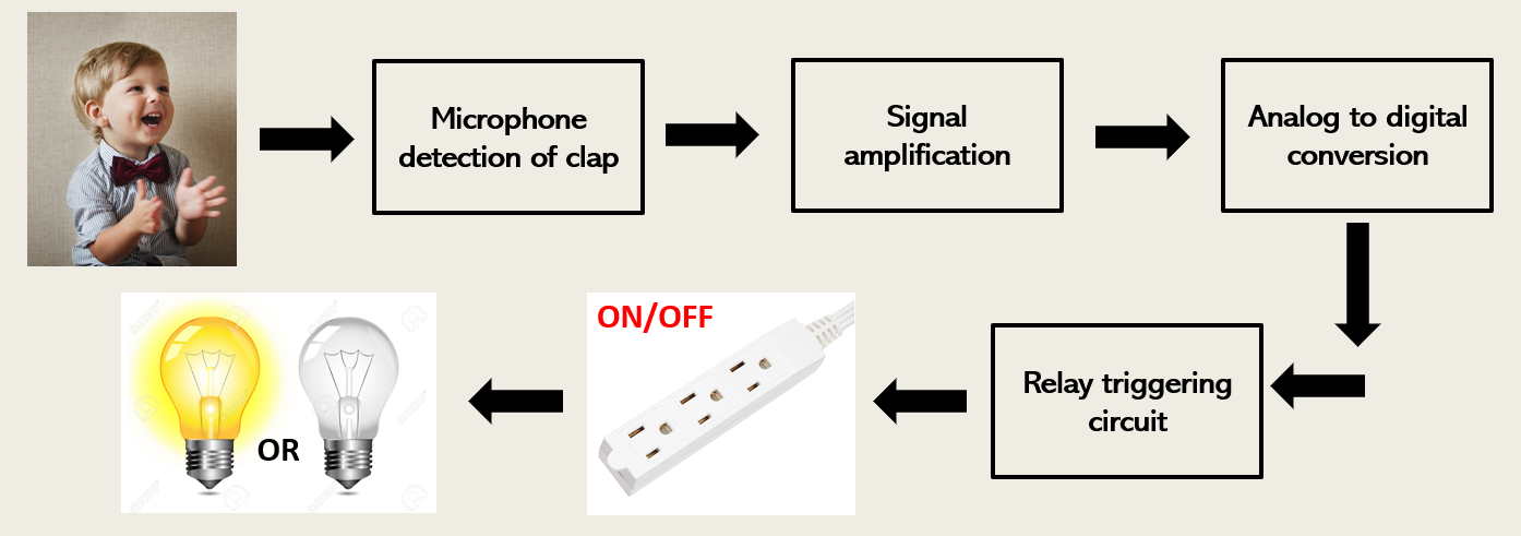
After graduating from FSU in 2019, this became my second project following the electronic MTG scoreboard that I made. Once again created as a gift for my best friend, Scott, this time I took at stab at making a clap activated switch. The clapper would serve as an interconnection between a wall outlet and any device that is powered via mains (i.e. lamp, fan, etc.). Once a clap is detected, the switch changes states and either cuts off or delivers power to the external device. This chain of events is demonstrated with the following block diagram, using a lightbulb as an example for an external appliance.
Concept and design
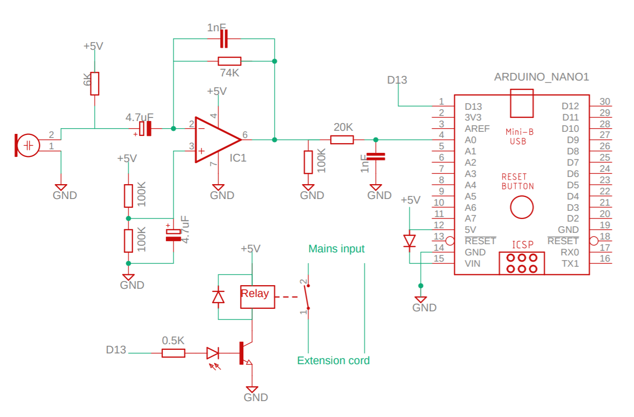
Here is the Eagle schematic for the clapper. Texas Instrument’s Single-Supply, Electret Microphone Pre-Amplifier Design was used as a reference for the signal amplification stage. The working principal of the device is as follows:
On the left-hand side of the schematic, an electret microphone responds to air pressure vibrations (i.e. sound waves) and produces a proportional voltage fluctuation at its output. A JFET is internally connected to provide a high-input impedance to the electret. Variations in the gate voltage thus produce variations in the drain current. The electret used was scavenged from an old AT&T answering machine.
An Operational Amplifier (OP-amp) is then used to amplify the low level drain current fluctuations as well as convert the current to a voltage (transimpedance); a LM358P OP-amp desoldered from a network board was employed. The output of the amplifier is connected to a low-pass filter to avoid any aliasing issues with the Arudino’s ADC.
This voltage is then read by an analog pin of the Arduino and converted to a digital signal. The program that continually samples this signal switches the clapper’s state once a predefined voltage limit is crossed on the input (i.e. a loud clap).
The clapper’s state is switched using a relay that is connected to mains power. The relay is energized once a S8050 NPN transistor switches on (a digital pin from the Arduino takes care of that). A flywheel diode is placed in parallel to the relay to avoid any damage to the transistor during commutation. Finally, an LED connected to the transistor’s base indicates the device’s ON/OFF state.
Programming
The greatest challenge for any clapper design is avoiding false positives, i.e. erroneous switching. To avoid these unwanted triggers, I employed 4 techniques software-wise:
Threshold level: high and low limit. The simplest solution -> as the signal coming into the ADC is AC with a DC offset, any voltage signal higher than a HIGH threshold or lower than a LOW threshold is allowed to trigger the relay circuitry.
Two claps required for trigger. This complicates significantly the program but helps in avoiding relay triggers from abrupt noise or vibration.
Restrict interval of time for 2nd clap to occur. If the 2nd clap is heard before X seconds, or heard after Y seconds, ignore and reset the system. The 2nd clap must thus be heard between X and Y seconds.
Silence requirement after 2nd clap. This criterion was included so that for example, music played next to the microphone would not trigger the system. Only 2 claps heard within a certain timeframe and nothing else would turn on/off the relay.
1
2
3
4
5
6
7
8
9
10
11
12
13
14
15
16
17
18
19
20
21
22
23
24
25
26
27
28
29
30
31
32
33
34
35
36
37
38
39
40
41
42
43
44
45
46
47
48
49
50
51
52
53
54
55
56
57
58
59
60
61
62
63
64
65
66
67
68
69
70
71
72
73
74
75
76
77
78
79
80
81
82
83
84
85
86
87
88
89
90
//Pin definitions
#define RELAY_STATE 2
#define AMP_SIGNAL 3

//Solution 1 --> Threshold levels
int reading;
int lowerLimit = 230;
int higherLimit = 660;

//Solution 2 --> 2 claps required
bool clap1=false;
bool clap2=false;

//Solution 3 --> Interval requirement
int clapShortInterval= 500;
int clapLongInterval = 1000;

//Solution 4 --> Silence requirements
int silenceShortInterval= 200;
int silenceLongInterval= 500;

//Timers
unsigned long checkClap;
unsigned long currentTimer;

void setup(){
  digitalWrite(RELAY_STATE,LOW);
  pinMode(RELAY_STATE,OUTPUT);
}

void loop() {
  checkReading();
  triggerRelay();
}

void switchRelay(){
  if(digitalRead(RELAY_STATE)==HIGH){
    digitalWrite(RELAY_STATE,LOW);
 }
  else{
    digitalWrite(RELAY_STATE,HIGH);
  }
}

void checkReading(){
  reading = analogRead(AMP_SIGNAL);
  Serial.println(reading);
}

void triggerRelay(){
  if ((reading > higherLimit || reading < lowerLimit) && clap1==false && clap2==false){
    clap1=true;
    checkClap=millis();
}

//Clap 1 is heard --> check for Clap 2
  while(clap1==true){
    currentTimer=millis();
    if (currentTimer-checkClap>=clapShortInterval && currentTimer-checkClap<= clapLongInterval){
      checkReading();
        if ((reading > higherLimit || reading < lowerLimit)&& clap2==false){
          clap2=true;
          clap1=false;
          checkClap=millis();
        }
    }
  //If Clap 2 is not heard within interval, reset the system
  else if (currentTimer-checkClap>clapLongInterval){
    clap1=false;
  }
}


//Clap 2 is heard --> check for silence
while(clap2==true){
  currentTimer=millis();
  if (currentTimer-checkClap>=silenceShortInterval){
      checkReading();
      if (currentTimer-checkClap>=silenceLongInterval){
        switchRelay();
        clap2=false;
        delay(1500); //avoids picking up relay switching (clicking) noise
    }
      //If there is noise after the silence interval, reset the system
      else if(reading > higherLimit || reading < lowerLimit && currentTimer-checkClap<silenceLongInterval ){
        clap2=false;
      }
    }
  }
}
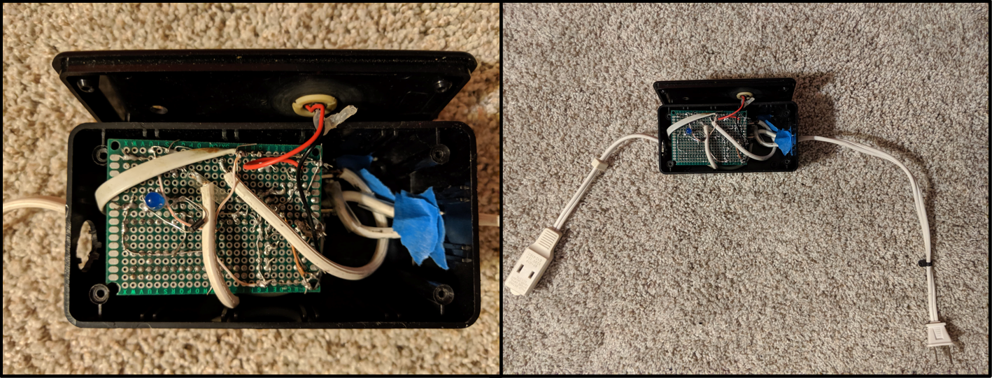
Soldering and enclosure
All components were soldered to a perfboard and power to the device was supplied with a 5V USB phone adapter. For the enclosure, a plastic black box was used with holes drilled in for placing the electret microphone, the indicator LED and the INPUT/OUTPUT extension cord cables.
Final product
And with that, another successful project in the books! Enjoy these videos of the clapper triggering. The device also functions as a knock/vibration detector as demonstrated in the second video.